OBDII Port Pinout Arrangement RACELOGIC Support Centre
The service manual typically includes an OBD2 pinout diagram specific to the make and model of the vehicle, highlighting any variations or unique features. Additionally, there are online resources and databases available that provide comprehensive OBD2 pinout information for various vehicle models.. OBD2 Diagnostic Connector Wiring. When.
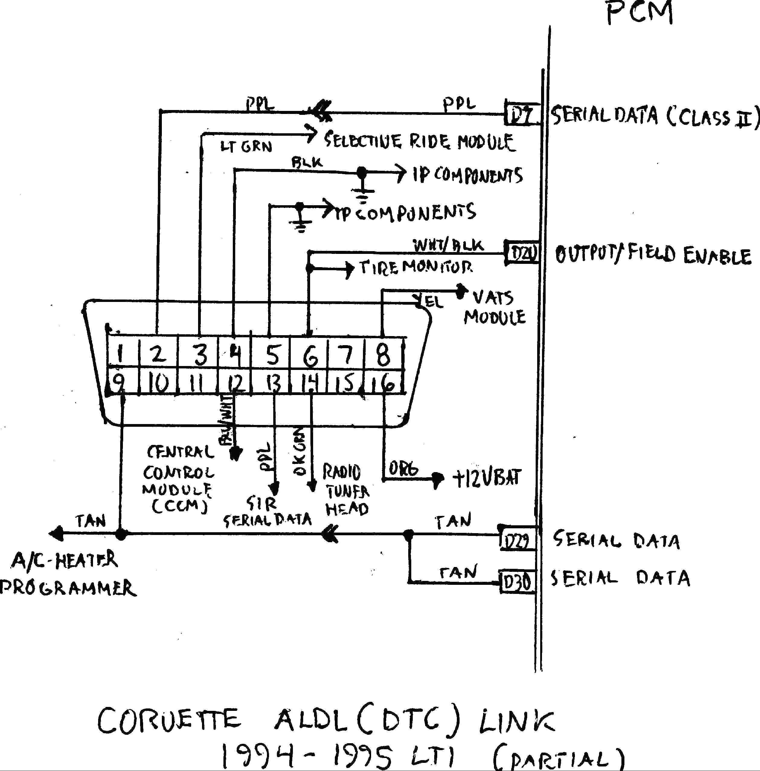
obd1 connector diagram
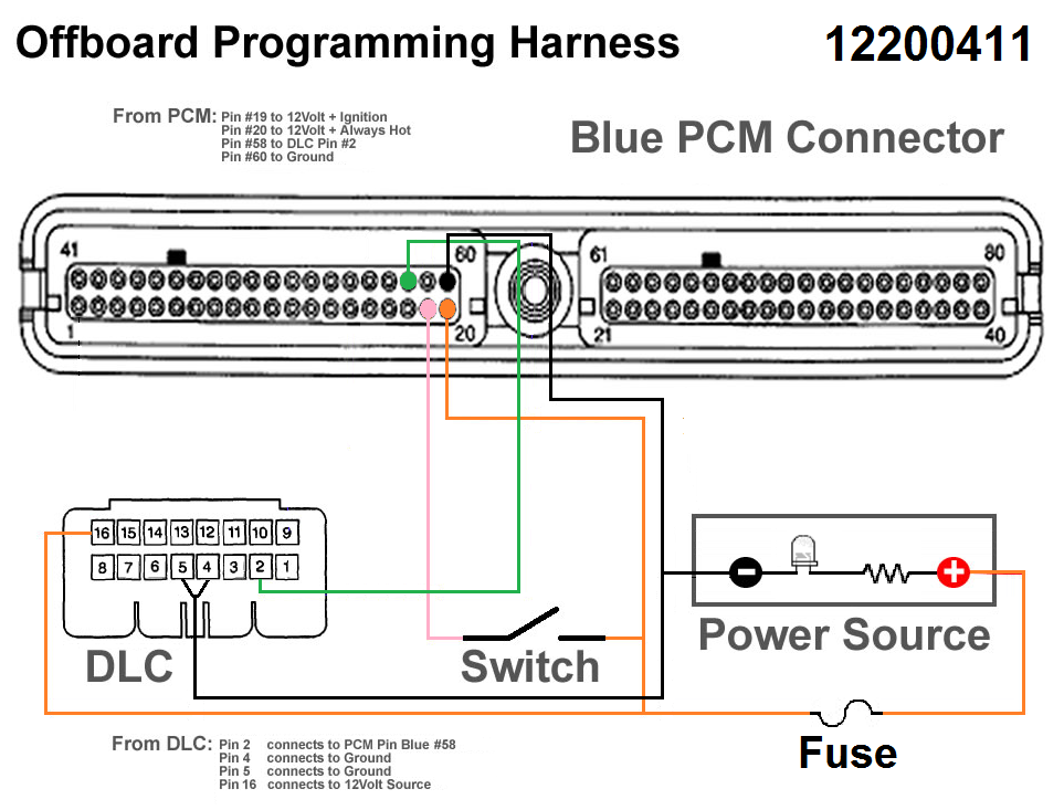
Step 1: Hook up pin 4 and Pin 5 (ground wires) to form a single wire. In a few cases, it might work separately. But if the equipment does not allow it, it can create problems in communication. Once hooked, you can connect it with PCM. Step 2: Pin 2 will go to port 58 on the blue connector on the PCM. Step 3: Connect Pin 10 and 16 to 12V battery.
obd 1 honda engine wiring
OBD II CONNECTOR WIRING FOR LS SWAPSToday we do a short tutorial on wiring your obd2 connector on your ls swap.OBD2 CONNECTOR: https://www.ebay.com/sch/i.htm.

obd2connectorshape OBD Station
¡Precios increíbles y alta calidad aquí en Temu. Envío gratuito en todos los pedidos. ¡Solo hoy, disfruta de todas las categorías hasta un 90% de descuento en tu compra.
OBD2 Technology The Definite Interpretation OBD Solaris
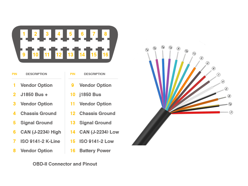
OBD-II connector specifications. The OBD-II specification provides for a standartized hardware interface - the female 16-pin (2x8) J1962 connector. Unlike the OBD-I connector, which was found under the hood of the vehicle, the OBD-II connector is located on the driver's side of the passenger compartment near the center console.
OBD2 Explained A Simple Intro (2021)
Power your simulator off of the supplied 12V power supply. Open up a serial terminal at 115200 bps, 8,N,1 connecting to the serial port the simulator is configured to. Configure the simulator to the protocol you desire to test. Connect to your ECU device (OBD-II board, CAN-Bus Shield, Raspberry Pi, etc.)
Obd2 Wiring Diagram Wiring Diagram
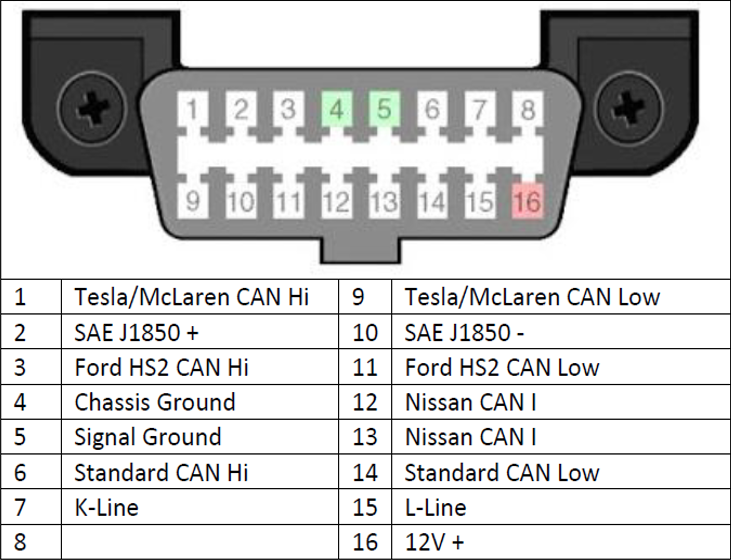
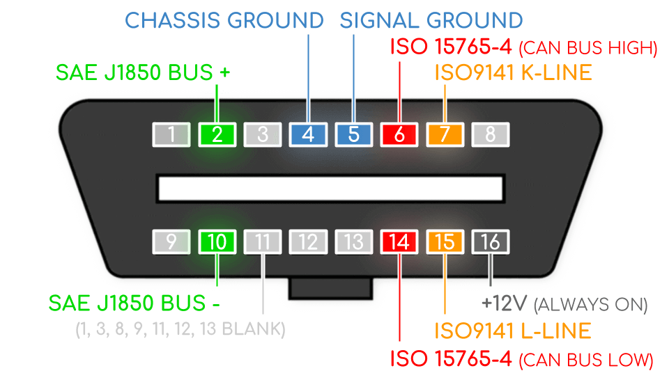
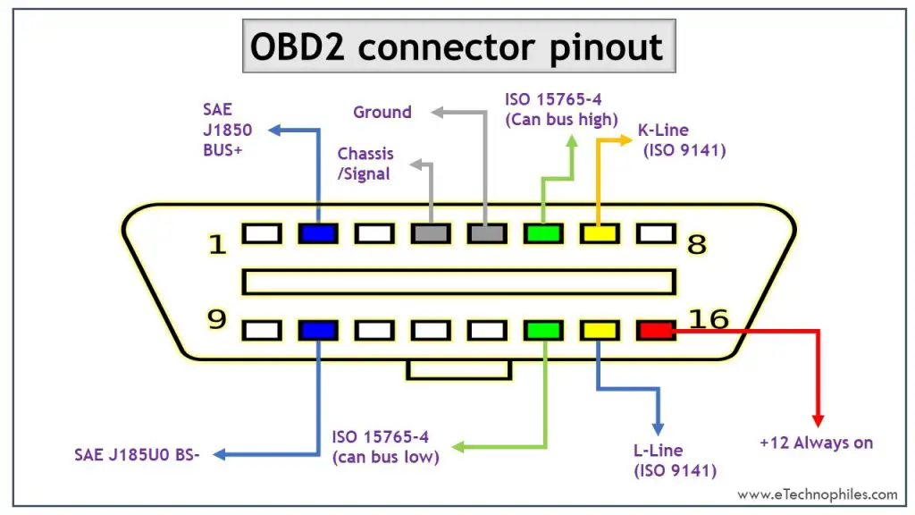
OBD 2 Pinout Explained. On-Board Diagnostics II, or OBD2, is a self-diagnostic and reporting system in modern vehicles. It consists of an Electronic Control Unit, several sensors, and indicator lights. The sensors inspect the various subsystems within the vehicle and report any faults and abnormalities to the ECU.
OBD2 Connector Pinout, Types & Codes(Explained)
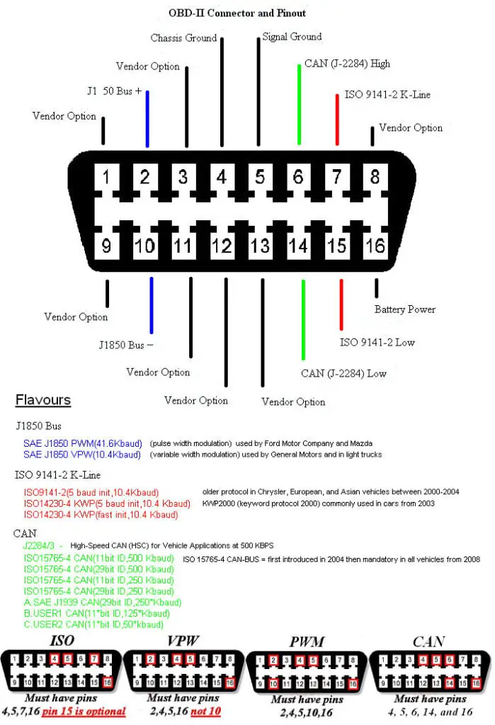
P1706 Park/Neutral Position (PNP) Switch. P1760 Overrun Clutch Solenoid Valve (Circuit) - Read Our Article On Automotive Circuit Testing For Help With This Nissan Check Engine Light Code. Some OBD-II cables schemes: OBD-2 ISO 9141-2 (14230-4, KWP2000) simple serial cable. OBD-2 J1850 PWM, J1850 VPW serial ELM327 cable.
Obd2 protocol pinout
The OBD connector is a vital link between your car's onboard computer (ECU) and external devices, like diagnostic scanners. Think of it as your car's personal doctor, helping mechanics and technicians diagnose and treat any issues that might arise.. • Single-Wire CAN (SAE J2411 / GMW3089) (33.3Kbps) • GM UART / ALDL (SAE J2740) (8192.
Obd2 protocol pinout
OBD2 is an onboard diagnostic system present in cars that collect data from a vehicle. To collect this data, the cars must have an OBD port installed in them. Using an OBD connecter, a technician may collect this data and analyze the errors in the car. But, to see how all of this works, let us first understand what an OBD port and connector is.
OBDII Male Opening Cable
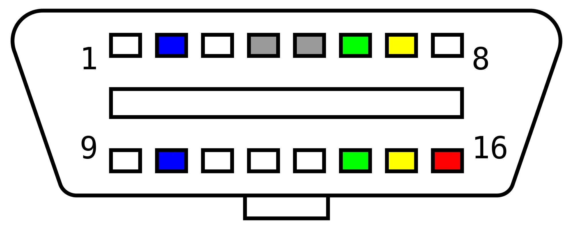
Diagrams OBD2 Connector Wire Colors provide a visual reference to identify the various wires and connections within an OBD2 system. This makes it easier to diagnose any problems and take corrective action quickly. With a diagram, it's easy to find out which connectors are used for specific components and understand how the electrical system.

OBD full form in Automobiles
The OBD-M-DB9-ES cord is 900mm long. ODB-16P Connector (Male) The wiring of the ODB-16P connector is designed such that it connects to the CANbus pins in an OBD-II automotive application. Internal Connection. The following table below indicates how the wiring of the OBD-M-DB9-F-ES is implemented. Pinout Diagram of OBD-II adapter cable Safety.
OBD2 pinout explained. Major car brands pinouts
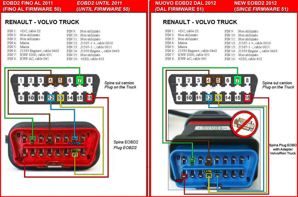
Some OBD-II cables schemes: OBD-2 ISO 9141-2 (14230-4, KWP2000) simple serial cable. OBD-2 J1850 PWM, J1850 VPW serial ELM327 cable. OBD-2 universal ISO 15765-4 CAN, SAE J1850 PWM, SAE J1850 VPW, ISO 9141-2, ISO 14230-4 and SAE J1939 diagnostic cable.

Wiring the MCP2515 Controller Area Network CAN BUS Diagnostics
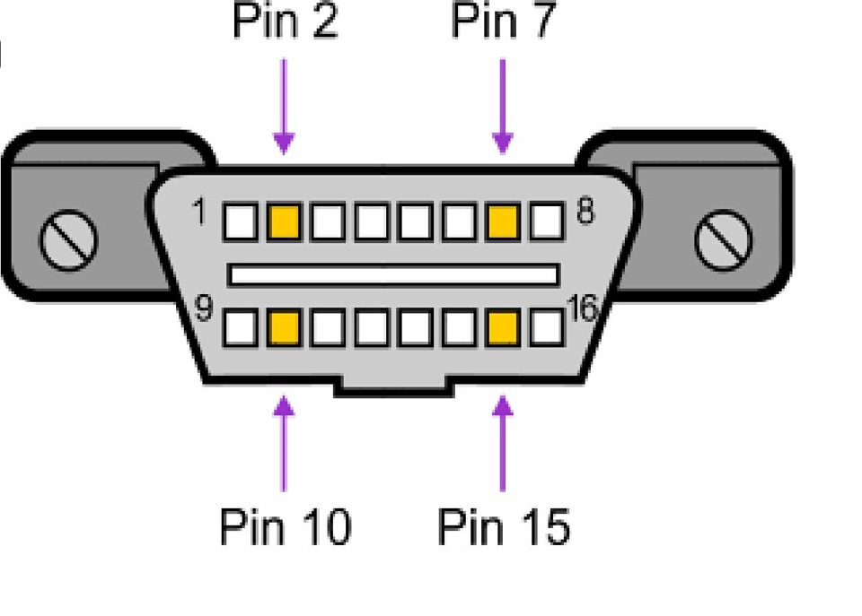
obd-II pinout for Buick, Chevrolet, Cadillac, Pontiac, GMC, Holden. The pinout should fit 47 devices/models. Click to list>. Pinout may be slightly different - depending on model. Most GM cars produced in 1996-2003 use J1850-VPW interface. GM cars produced in 2003-2006 use J1850-VPW interface or CAN. Most cars produced after 2006 are equipped.
gm obd wiring diagram
OBD-II Data Link Connector (DLC)Get the book here: https://www.createspace.com/4338259Describes the OBD2 connector also called the DLC, what each PIN does, a.

Usb Wiring Diagram Homemade Obd2 To Usb Cable Building A Tuneecu Cable Adventure Rider / Obd2
Using the wiring diagram as a guide, connect the prepared wires to the corresponding pins or terminals on the OBD2 port. Be careful to make secure connections and ensure that the correct wires are matched to the correct pins. You may need to use a small screwdriver or electrical connectors to secure the wires in place.